Data Conditioning & Pre-processing

Preprocessing phase (Steps 1.1 to 1.4) is the primary goal is to ensure data integrity and prepare the signal for intensive processing while preserving the relative amplitude. Here are the specific parameters to test and the controlling factors for each step:
Data Conditioning & Pre-processing
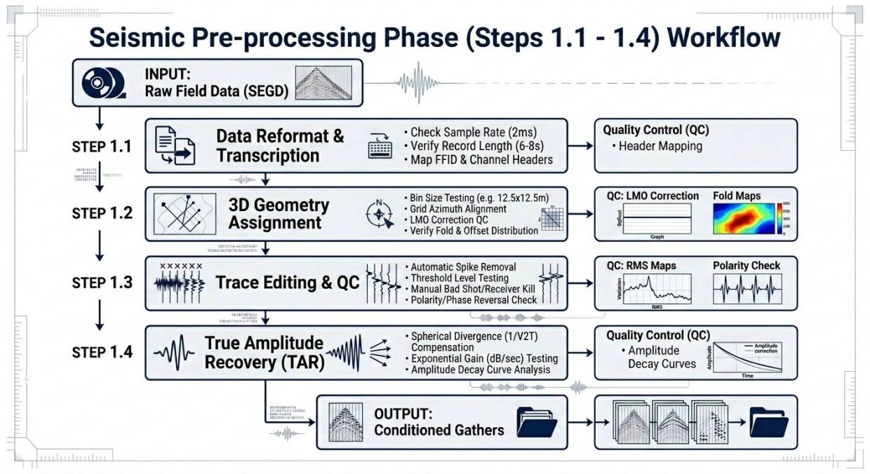
1. Data Transcription and Reformatting
Goal: Converting raw field data (SEGD) to a processing-ready format (SEGY/Internal) without data loss.
Parameters to Test:
1. Sample Rate: Ensure it matches field recording (e.g., 2ms). Test if resampling is needed for later stages.
2. Record Length: Verify that the full target depth is captured (e.g., 6.0s or 8.0s).
Controlling Parameters/QC:
1. Header Mapping: Crucial to check if FFID (Field File ID), Channel Number, and Shot ID are correctly mapped to trace headers.
2. Data Integrity: Identifying corrupted files or "parity errors" from field tapes/disks.
2. Geometry Assignment and QC
Goal: Establishing the spatial relationship between sources and receivers.
Parameters to Test:
1. Bin Size: Testing the optimal grid (e.g., 12.5m x 12.5m vs. 25m x 25m) based on Fresnel zone and spatial aliasing.
2. Grid Azimuth: Aligning the grid with the dominant structural strike or dip of the reservoir.
Controlling Parameters/QC:
1. LMO (Linear Moveout) Correction: This is the ultimate test. If the first breaks align linearly after LMO, the geometry is correct.
2. Source/Receiver Deviations: Checking for errors in GPS coordinates vs. nominal field positions.
3. Fold Coverage: Generating "Fold Maps" to identify holes in coverage caused by skipped shots or obstacles.
3. Trace Editing (Data Cleaning)
Goal: Removing non-geological noise that could contaminate the stack.
Parameters to Test:
1. Threshold Levels: Determining the amplitude limit for "Spike" detection (automatic removal of high-energy bursts).
2. Frequency Cut-offs: Identifying mono-frequency noise (e.g., power line hum at 50/60 Hz).
Controlling Parameters/QC:
1. RMS Amplitude Maps: Visualizing the energy of every trace. Dead channels will show as zero; noisy channels will show as "hot spots."
2. Polarity Check: Identifying traces with reversed phase (180-degree flip) caused by faulty wiring in the field.
3. Swell Noise/Wind Noise: Assessing if time-variant surgical muting is required for specific traces.
4. Gain Recovery / True Amplitude Recovery (TAR)
Goal: Compensating for the natural loss of energy as the seismic wave travels deeper. Parameters to Test:
1. Spherical Divergence Correction (1/v^2t): Testing different velocity functions (v) to see which one best balances amplitude from shallow to deep.
2. Absorption Compensation (dB/sec): Testing an exponential gain constant to compensate for inelastic absorption of the earth.
Controlling Parameters/QC:
1. Amplitude Decay Curves: Plotting Amplitude vs. Time. The goal is a "flat" curve where deep reflections have similar energy levels to shallow ones (without boosting noise).
2. Window Selection: Ensuring the gain begins exactly at the first arrival (break) to avoid boosting pre-arrival noise.
3. Brute Stack Comparison: Comparing stacks with and without TAR to ensure that deep reflectors are visible but not "over-blown." For the *Preprocessing phase (Steps 1.1 to 1.4), the primary goal is to ensure data integrity and prepare the signal for intensive processing while preserving the relative amplitude.