2️⃣ First Arrival Picking & Time–Depth Calibration

First Break Picking
Pick Downgoing P-wave arrival at each depth Accuracy here is everything.

Checkshot / Time-Depth Curve
From picked first arrivals Compute cumulative travel time vs depth and Derive:
- Interval velocity
- RMS velocity
📌 This is the backbone of VSP value to surface seismic.
Align downgoing arrivals vertically often done by flattening first breaks Purpose:
- Makes wavefield separation easier
- Improves S/N
3️⃣ Wavefield Separation & Deconvolution

Downgoing / Upgoing Separation
In VSP data (especially zero-offset VSP), separating downgoing and upgoing wavefields is a fundamental preprocessing step before corridor stacking, deconvolution, and migration.
Methods:
1) Median filter in depth
Advantages
✔ Very simple
✔ No FFT required
✔ Good for quick QC
Limitations
✖ Window-size dependent
✖ Lower accuracy
✖ Not robust for complex wavefields
2) FK (f-kz) filtering
Advantages
✔ Simple
✔ Fast
✔ Works well when dips are clearly separated
Limitations
✖ Fails if wavefields overlap
✖ Requires regular depth sampling
✖ Sensitive to aliasing
3) Model-based separation like Tau-pi filtering
Advantages
✔ Better separation than FK
✔ Handles multiple dips
✔ More robust for complex data
Limitations
✖ Higher computational cost
✖ Needs regular depth sampling
Outputs:
- Downgoing wavefield (direct arrivals)
- Upgoing wavefield (reflections)
📌 Upgoing wavefield ≈ “reflection seismic recorded in the well”

Deconvolution (Often Corridor Decon)
VSP deconvolution is a signal processing step applied to Vertical Seismic Profile (VSP) data to:
- Compress the source wavelet
- Improve temporal resolution
- Remove source signature and reverberations
- Enhance primary reflections
- Stabilize amplitude and phase
In VSP, especially zero-offset VSP, downgoing waves contain strong source signature and multiples. Deconvolution helps convert the recorded wavelet into a sharper spike-like response, making interpretation and inversion more reliable. Downgoing waves are used to extract VSP deconvolution operator. This operator is convolved on flattend upgoing waved.
4️⃣ Corridor Stack

What is Corridor Stack?
- Stack of upgoing reflections
- Taken in a time window just after first arrivals
- Produces a 1D seismic trace at the well
📌 This is the best seismic–well tie trace you can get.
Why Corridor Stack Matters
- Ties synthetic seismograms
- Validates seismic polarity
- Confirms wavelet phase
- Reduces multiples
👉 Many interpreters trust corridor stack more than surface seismic at the well.
4️⃣ VSP Component rotation

4️⃣ VSP Component rotation

VSP component rotation
VSP component rotation is a processing step where the recorded 3-component seismic data (X, Y, Z) are mathematically rotated into a physically meaningful coordinate system aligned with the wave propagation direction.
Component rotation transforms the original geophone components (X, Y, Z) into new axes such as Radial (R), Transverse (T), and Vertical (Z) or P-SV-SH directions, so that seismic wave modes can be better separated and interpreted.
Why it is needed in VSP
Downhole geophones are rarely perfectly aligned with the source direction. Because of this:
- Energy from the P-wave can appear on all components.
- S-waves may mix between horizontal components.
- Wavefield separation (downgoing vs upgoing) becomes difficult.
By rotating the components:
- P-wave energy concentrates on the radial direction
- SV energy appears mainly on the vertical–radial plane
- SH energy concentrates on the transverse component
5️⃣ VSP Imaging & Migration
VSP-CDP Transform & Migration
Maps upgoing energy to:
- Reflection points in the subsurface
Used for:
- Zero-offset imaging
- Offset VSP imaging
Methods:
- Kirchhoff migration
- Wave-equation migration
- Reverse-time migration (RTM) for VSP
📌 Requires:
- Accurate velocity model
- Correct anisotropy
Result:
- High-resolution image near and below the well

VSP-CDP Transform & Migration
The VSP–CDP transform is a processing technique used to convert Vertical Seismic Profile (VSP) data from the depth-time domain at the well location into a Common Depth Point (CDP) domain that is directly comparable with surface seismic data. In VSP, seismic energy is recorded downhole, providing high-resolution information near the well, but it is spatially limited. The VSP–CDP transform repositions and maps these recorded wavefields along reflection points in the subsurface, effectively creating a seismic image that extends laterally away from the borehole. This allows geophysicists to tie well data to surface seismic sections, improve structural and stratigraphic interpretation, and enhance the reliability of reservoir characterization by combining the vertical accuracy of VSP with the lateral coverage of conventional seismic data.
Q Estimation (Attenuation)
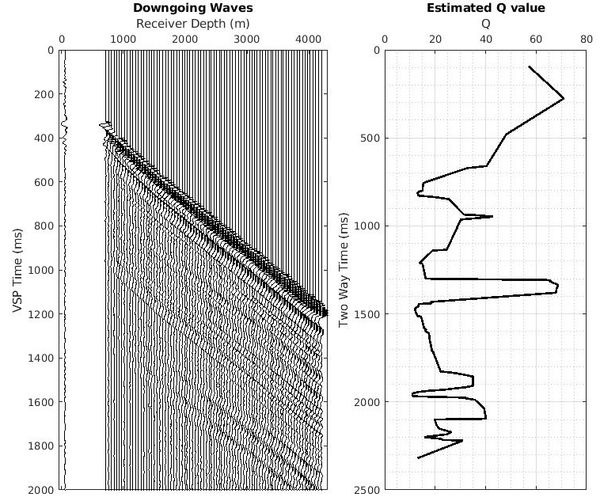
VSP Q estimation refers to the process of measuring seismic attenuation (the loss of energy) using Vertical Seismic Profile (VSP) data recorded in a borehole. The parameter Q (quality factor) describes how quickly seismic waves lose amplitude and high-frequency content as they travel through the subsurface. In VSP, Q is typically estimated by analyzing the downgoing wavefield—often using methods like spectral ratio or frequency decay between receivers at different depths. Because VSP data are recorded close to the propagation path, they provide more reliable and higher-resolution attenuation measurements than surface seismic. Accurate Q estimation is essential for amplitude correction, wavelet stabilization, and improving the fidelity of seismic imaging and inversion results.
Using downgoing wavefield:
- Spectral ratio
- Pick-frequency
- Centroid frequency shift
Output:
- Q vs depth
- Q anisotropy (multi-azimuth VSP)